Linux Home Server HOWTO
Chapter 6 - Firewall Concepts


With all the possible security threats roaming around the Internet today, a security firewall should be considered a mandatory necessity for any computer systems connected to the Internet. A firewall is a networking device which is used to separate private networks from external access by providing a certain level of security rules and controls.

A simple firewall can be configured to block all access to certain networks, workstations and communication ports. A more complex firewall is capable of inspecting each individual packet that attempts to pass through it and ensures that they are correctly formatted and appropriate to the services provided for (or by) the internal network, this is called a packet filtering firewall.

This chapter will explain some of the concepts for iptables and packet forwarding which can be used to secure your private network. The example configurations provided in each section are only designed to provide an introduction into each of those specific sections, while an example firewall script has been included which will provide simple but effective security for your networked system.


Many of the newer broadband modems provide built-in firewall features that allow for stateful packet inspection and detailed network address translations, which are capable of providing a high security level for your internal network.


Packet Forwarding
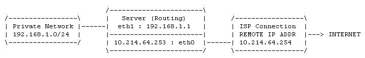
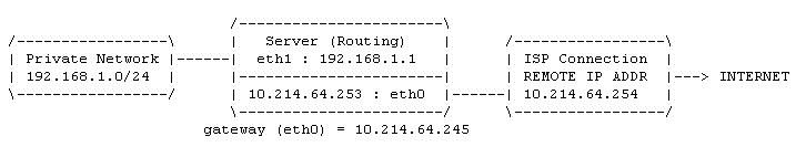
Packet forwarding is a simple concept where the server allows data packets to pass from one network to another. As with the diagram below, packets from the private network are allowed to be forwarded through the server and out to the ISP and vice versa.


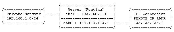
There are a few initial considerations. First, the server must have networks or gateways defined in its routing table so it can make an informed decision where the packet needs to be passed to. Second, the server must have packet forwarding enabled. Thirdly, if the routed packets came from an RFC1918 private subnet, they must be translated into globally routed IP addresses (NAT covered later) before they will be accepted out on the Internet.

Packet forwarding can be enabled either manually as required by the superuser, or automatically when the system starts the networking service. To manually enable or disable packet forwarding, use the respective commands listed below.


[bash]# echo 1 > /proc/sys/net/ipv4/ip_forward


[bash]# echo 0 > /proc/sys/net/ipv4/ip_forward


To enable automatic packet forwarding for whenever the network service is active, make the following changes in your /etc/sysctl.conf file.


[bash]# vi /etc/sysctl.conf


net.ipv4.ip_forward = 1


It is common practice for users to have manual control over packet forwarding, and to active or disable the function within their firewall control scripts. However setting packet forwarding to start automatically will be more suitable for a dedicated server.


Packet Filtering
Packet filtering is also a reasonably simple concept (true), however it can be very daunting for new users that don't fully understand how it works, so let's cover the basics first and build it up.

In packet forwarding the kernel is either allowed to move packets between different subnets or is not, and if it is, the decisions are made from the kernel's routing table. In packet filtering an application called iptables (http://www.netfilter.org/) stores a list of programmed rules which are individually tested against every packet that either tries to enter, pass through, or exit any of the system's network devices. Each rule is used to test the packet in a sequential order and if the packet matches any of the rules it is either accepted or rejected depending on the global policy and rule definitions. iptables is your firewall application and is one of the networking frameworks for your Linux kernel.

iptables essentially has this name because it stores the rulesets into a group of three tables which each provide different capabilities depending on the rules and the order they are applied. We will only examine the filter and nat tables here, the mangle table is used for specialised packet alteration which is beyond our scope. The following table displays the filter iptables and the three built-in chains.

Table Name
Chain Name
Chain Details
filter
INPUT
For any packet coming into the system
FORWARD
For any packet that is being routed through the system
OUTPUT
For any packet that is leaving the system
To list the filter table and its rules you can use the following command.


[bash]# iptables -t filter -nvL


The filter table is the default table when working with iptables, so there is no need to add '-t filter' at the command prompt.


[bash]# iptables -nvL


Chain INPUT (policy ACCEPT 0 packets, 0 bytes)
pkts bytes target - prot - opt - in - out - source - destination

Chain FORWARD (policy ACCEPT 0 packets, 0 bytes)
pkts bytes target - prot - opt - in - out - source - destination

Chain OUTPUT (policy ACCEPT 0 packets, 0 bytes)
pkts bytes target - prot - opt - in - out - source - destination


You should see an output similar to above, if not then stop the iptables service and output the table again. From the listing you can see the three built in chains, and their default policies are all set to ACCEPT, which means the firewall is inactive.


[bash]# /etc/init.d/iptables stop


The output from the top listing does not provide much information, so let's populate the table with some of our own rules. Type the following commands at the prompt then output a listing of the table again.

01- [bash]# iptables -P INPUT DROP
02- [bash]# iptables -P FORWARD DROP
03- [bash]# iptables -P OUTPUT DROP
04- [bash]# iptables -A INPUT  -i lo -j ACCEPT
05- [bash]# iptables -A OUTPUT -o lo -j ACCEPT
06- [bash]# iptables -A INPUT  -i ppp0 -p tcp --sport 80 -j ACCEPT
07- [bash]# iptables -A OUTPUT -o ppp0 -p tcp --dport 80 -j ACCEPT
08- [bash]# iptables -A INPUT  -i eth1 -s 192.168.1.0/24 -p tcp --dport 3128 -j ACCEPT
09- [bash]# iptables -A OUTPUT -o eth1 -d 192.168.1.0/24 -p tcp --sport 3128 -j ACCEPT

[bash]# iptables -nvL
01-

04-
06-
08-

02-


03-

05-
07-
09-
Chain INPUT (policy DROP 0 packets, 0 bytes)
 pkts bytes target  prot opt in  out  source          destination
    0     0 ACCEPT  all  --  lo   *   0.0.0.0/0       0.0.0.0/0
    0     0 ACCEPT  tcp  --  ppp0 *   0.0.0.0/0       0.0.0.0/0   tcp spt:80
    0     0 ACCEPT  tcp  --  eth1 *   192.168.1.0/24  0.0.0.0/0   tcp dpt:3128

Chain FORWARD (policy DROP 0 packets, 0 bytes)
 pkts bytes target  prot opt in  out  source          destination

Chain OUTPUT (policy DROP 0 packets, 0 bytes)
 pkts bytes target  prot opt in  out  source          destination
    0     0 ACCEPT  all  --  *   lo   0.0.0.0/0       0.0.0.0/0
    0     0 ACCEPT  tcp  --  *   ppp0 0.0.0.0/0       0.0.0.0/0      tcp dpt:80
    0     0 ACCEPT  tcp  --  *   eth1 0.0.0.0/0    192.168.1.0/24  tcp spt:3128
The nine commands which you typed above have been numbered along with their output so they can be easily identified in the second table.

Lines 01-03: The first three commands set the default (-P) policy on all the chains to DROP everything, unless suitable rules inside the chain will ACCEPT them. This is the most secure method of filtering as any packet that is now to pass through any of the chains, must have a specific rule written for it.

Lines 04-05: These two commands have (-A) appended two ACCEPT rules. The OUTPUT rule (05) allows any packet to (-o) leave via the loopback device and the INPUT rule (04) allows packets to re-enter (-i) via the loopback.

Because the chains are using a default DROP policy, they restrict the server from accessing any of its own services running on the local host, like DNS. A basic rule like this allows the server to access all loopback services without restriction.

Lines 06-07: The next two (-A) appended rules are more specific, lets look at the outbound one first. The OUTPUT rule (07) specifies that any packet going out the (-o) ppp0 interface using (-p) protocol TCP is ACCEPTed if its going to port 80. The INPUT rule (06) specifies that any packet coming in the (-i) ppp0 interface using (-p) protocol TCP is ACCEPTed if its coming from port 80.

You should be able to pick this up, it says that we are allowed to access external web servers from our own server, but there are no forward rules for the internal network to surf the Internet. We should also allow our internal network the ability to access external web servers too shouldn't we? Let's look at the next rules then.

Lines 08-09: The last INPUT rule (08) which has been (-A) appended to the chain allows any packets from the (-s) source network of 192.168.1.0/24 if they enter through the (-i) eth1 device and if they are the TCP (-p) protocol and are going to the (--dport) destination port of 3128. The matching OUTPUT rule (09) has been (-A) appended to the chain and allows any packets that are going out (-o) the eth1 interface to (-d) destination network 192.168.1.0/24 using the TCP (-p) protocol if it came from the (--sport) source port of 3128.

These two are fairly detailed rules, they say that anyone on the internal network (192.168.1.0/24) is allowed to send packets to the squid proxy server (3128) through the internal eth1 interface and the results can be returned to the workstation.

If you use a strict DROP policy like above, its important to note that you may need two rules that complement each other in order for data to flow out and back in again.

A Walk Through

To better understand the above filtering example, its best to walk the configuration through the same way a packet would be subject to the filtering table's definitions, one rule at a time. Remember, every packet of data has certain attributes, source/destination addresses, source/destination ports, the interfaces they are coming in and out and the type of protocol being used, the filtering will reject any packet whose attributes dont match any of the rules in our chains.

A person using the workstation (in the network example below) wishes to access the resources of the web server located on the Internet, can a direct connection be established? No, all the policies are set to DROP and there is no FORWARD rules defined, so it simply can not occur.

Can the proxy server access the web server on the Internet? Yes, the proxy server has the rights to access anything which is TCP based operating at port 80 out through the ppp0 link, which is to a web server. Can you see the ACCEPT rules for the packet's attributes in the complementing INPUT and OUTPUT chains?

Photobucket


The only way now for the workstation to access anything, is via the proxy server application running at port 3128, which in turn can access any web server resources on the Internet and return the requested information to the workstation. Are the required rules in the table?

How does this work without any forwarding rules? Easy, the proxy server is an application that requests resources on behalf of a client, so the request comes into the proxy from the client, and now the request goes out to the web server from the proxy, as though it was requesting the information itself. This happens at the application layer, because its the proxy application which forwards the clients original request, so forwarding at the IP layer is not required here.

Hopefully you have been able to pick up the filtering concepts mentioned above, if you have, well done. The proxy server situation was a little tricky, but was introduced to give you an understanding that particular packets and resources can still be shaped to suit your security requirements by incorporating them into your network design.

Thats a brief introduction to packet filtering, the ability to write and chain together rules that selectively accept or deny any packets that do not meet the security requirements for your network.

What happens to the filter table when you type these following commands? View the table's output after each one and see if you can recognise the effects of the rules, and which direction the packets can pass (i.e., are they going to an internal or external resource). View "man iptables" for further assistance.

[bash]# iptables -I INPUT  2 -i ppp0 -p tcp --dport ftp -j ACCEPT
[bash]# iptables -I OUTPUT 2 -o ppp0 -p tcp --sport ftp -j ACCEPT

[bash]# iptables -D INPUT  -i ppp0 -p tcp --sport 80 -j ACCEPT
[bash]# iptables -D OUTPUT -o ppp0 -p tcp --dport 80 -j ACCEPT

[bash]# iptables -A INPUT  -p icmp --icmp-type any -j ACCEPT
[bash]# iptables -A OUTPUT -p icmp --icmp-type any -j ACCEPT

[bash]# iptables -I INPUT  -m state --state INVALID -j LOG --log-prefix "INVALID Input: "
[bash]# iptables -I INPUT  -m state --state INVALID -j DROP

[bash]# iptables -F
[bash]# /etc/init.d/iptables restart
Network Address Translation

Network Address Translation (NAT) is the ability to change a data packets destination or source IP address on-the-fly, so the packet looks like it came from (or is going to) a different address than the original (also works on port numbers).

There are many reasons why we should use NAT, here are a few:
  • Frees the requirement to use large amounts of 'real' IP addresses (cheaper),
  • Allows packets from a private (RFC1918) network to be globally routed out to the Internet,
  • Allows packets on the Internet to be routed into a private (RFC1918 network,
  • It masks the true amount of private workstations, as all external traffic appears to come from the one source,
  • It allows inbound traffic to be sent to different internal hosts (bastions) depending on the resources requested, and
  • It does not disclose any security details of the internal private network.
The iptables package also provides support for NAT and has a built-in nat table just for that purpose. Below is a listing of the default chains that are found in the nat table and an explanation of how they are applied.
Table Name
Chain Name
Chain Details
nat
PREROUTING
For altering packets as they are entering the system (before filter
INPUT)
POSTROUTING
For altering packets as they are exiting the system (after filter
OUTPUT)
OUTPUT
For altering  packets before leaving the local system (before the
routing table)
As the naming suggests, the PREROUTING and POSTROUTING chains are applied before or after any kernel routing decisions are made, so the packets can then be routed to match any new changes which have been made to the destination or source addresses. To list the contents of the nat table, issue the following command at the prompt.
[bash]# iptables -t nat -nvL
Source NAT Source NAT deals with changing the source address of any packets that pass through the NAT device, assuming they meet the criteria of the specified policies and chains. This allows workstations on a private network to send data packets through the NAT device which changes the source address in the packet's header before sending the packet onto the Internet. When the packet reaches its destination and is processed, the distant host returns the packet using the adjusted address as the new destination address, and delivers it back to the NAT device. The NAT device stores a list in memory of all the packets it adjusts, so when they are returned, the packets can be redirected to the real originator of the packets on the internal private network. Source NAT can be written for inbound and outbound packets, but are more commonly used for outbound. For a packet to be subject to SNAT, lets consider the following details:
  • The packet has meet at least one rule in all three filter chains (INPUT, FORWARD, OUTPUT),
  • The packet has been checked against the kernel routing table, and a decision on where to route has been made,
  • As the packet leaves the NAT device, the source address is changed to the NATs external IP address,
  • The NAT device remembers the real owner of the packet.
It all sounds rather confusing, so lets go straight to an example. Type the following rules at the command prompt and then display the contents of the filter and nat tables with the last command (typed as one line).
01- [bash]# iptables -P INPUT ACCEPT
02- [bash]# iptables -P FORWARD DROP
03- [bash]# iptables -P OUTPUT ACCEPT
04- [bash]# iptables -A FORWARD -i eth1 -o ppp0 -s 192.168.1.0/24 -p tcp --dport 80 -j ACCEPT
05- [bash]# iptables -A FORWARD -i ppp0 -o eth1 -d 192.168.1.0/24 -p tcp --sport 80 -j ACCEPT
06- [bash]# iptables -t nat -A POSTROUTING -o ppp0 -s 192.168.1.0/24 -j SNAT --to-source 123.123.123.2
07- [bash]# echo 1 > /proc/sys/net/ipv4/ip_forward

[bash]# iptables -nvL ; iptables -t nat -nvL
,
01-


02-

04-
05-

03-


06-

Chain INPUT (policy ACCEPT 0 packets, 0 bytes)
 pkts bytes target   prot opt in    out    source        destination

Chain FORWARD (policy DROP 0 packets, 0 bytes)
 pkts bytes target prot opt in   out   source         destination
   0    0   ACCEPT tcp  --  eth1 ppp0  192.168.1.0/24 0.0.0.0/0    tcp dpt:80
   0    0   ACCEPT tcp  --  ppp0 eth1  0.0.0.0/0    192.168.1.0/24 tcp spt:80

Chain OUTPUT (policy ACCEPT 0 packets, 0 bytes)
 pkts bytes target prot opt in   out   source         destination

Chain PREROUTING (policy ACCEPT 0 packets, 0 bytes)
 pkts bytes target prot opt in   out   source         destination

Chain POSTROUTING (policy ACCEPT 0 packets, 0 bytes)
 pkts bytes target prot opt in   out  source         destination
   0    0   SNAT   all  --  *   ppp0  192.168.1.0/24 0.0.0.0/0 to:123.123.123.2

Chain OUTPUT (policy ACCEPT 0 packets, 0 bytes)
 pkts bytes target prot opt in   out  source         destination
Lines 01-03: The first three commands have now defined the global policies for the three built-in chains for the filter table. To keep the example a little easier to understand, we are going to accept everything that is classed as INPUT or OUTPUT, and for security we are dropping anything trying to pass through (FORWARD) the NAT unless we allow it. Lines 04-05: The two forward rules are quite specific. Rule 04 says that any packet that comes in (-i) the eth1 interface and goes (-o) out the ppp0 device from the (-s) source network of 192.168.1.0/24 can be ACCEPTed if its going to (--dport) destination port 80; a web server. Rule 05 is the matching rule allowing the packet to return back through the NAT. We don't have any INPUT or OUTPUT restrictions here, so we only need to write and match rules that allow packets to pass through (FORWARD) the NAT. In the diagram below, when a HTTP(80) request comes from the private network, it is allowed to pass through the NAT and continue to the web server out on the Internet. But what are the packet's attributes? Its source address is still 192.168.1.x, so when it reaches its destination, the web server does not know where it came from because its a private non-routable RFC1918IP address, so the server will probably just drop it. No packets will ever be returned.
Photobucket
Line 06: This rule is our solution to the above problem. This rule is applied after the routing decisions have been made and the packet is about to depart for the web server out on the Internet. It says, any packet that goes (-o) out the ppp0 interface from the (-s) 192.168.1.0/24 network is to have the source address rewritten as 123.123.123.2. Now when the packet reaches the Internet web server, it can be processed normally and returned to 123.123.123.2 (the NAT device), where it will automatically be rewritten again and sent back to the original workstation on the internal private network. Line 07: This command tells the kernel that it is allowed to forward packets between any of its network devices. These packets are still subject to the iptables rulesets. Some important points about SNAT to remember are:
  • SNAT is used in the POSTROUTING chain after the kernel routing decisions have been made,
  • Forwarding rules need to be suitable to allow packets in both directions,
  • The "--to-source" address should be the external IP address which will be visible on the packets return, and
  • SNAT should not be used for dynamic links where the IP address is likely to change (see masquerading, next).
IP Masquerading Put simply, masquerading is a form of SNAT which should be used for all dynamic interfaces where the IP address is likely to be different each time we connect. This is perfect for our dynamic IP broadband accounts, and saves having to rewrite large SNAT rules each time we connect to the Internet. SNAT remembers connection state information (to a degree) if a static connection was to drop, however using masquerading the connection state information is reset each time the interface is (de)activated. Masquerading automates SNAT for dynamic IP connections. Because masquerading is so easy (true) we are going to use some state tracking attributes in our rules. Type the following rules at the command prompt and display a listing of the filter and nat tables.
01- [bash]# iptables -P INPUT ACCEPT
02- [bash]# iptables -P FORWARD DROP
03- [bash]# iptables -P OUTPUT ACCEPT
04- [bash]# iptables -A FORWARD -i ppp0 -m state --state ESTABLISHED,RELATED -j ACCEPT
05- [bash]# iptables -A FORWARD -i eth1 -o ppp0 -s 192.168.1.0/24 -j ACCEPT
06- [bash]# iptables -t nat -A POSTROUTING -o ppp0 -s 192.168.1.0/24 -j MASQUERADE
07- [bash]# echo 1 > /proc/sys/net/ipv4/ip_forward

[bash]# iptables -nvL ; iptables -t nat -nvL

01-


02-

04-
05-

03-


06-


Chain INPUT (policy ACCEPT 0 packets, 0 bytes)
 pkts bytes target prot opt in   out  source          destination

Chain FORWARD (policy DROP 0 packets, 0 bytes)
 pkts bytes target  prot opt in   out  source         destination
   0    0   ACCEPT  all  --  ppp0  *   0.0.0.0/0      0.0.0.0/0 state REL,ESTAB
   0    0   ACCEPT  tcp  --  eth1 ppp0 192.168.1.0/24 0.0.0.0/0

Chain OUTPUT (policy ACCEPT 0 packets, 0 bytes)
 pkts bytes target  prot opt in   out  source         destination

Chain PREROUTING (policy ACCEPT 0 packets, 0 bytes)
 pkts bytes target  prot opt in   out  source         destination

Chain POSTROUTING (policy ACCEPT 0 packets, 0 bytes)
 pkts bytes target      prot opt in   out  source         destination
   0    0   MASQUERADE  all  --  *    ppp0 192.168.1.0/24 0.0.0.0/0

Chain OUTPUT (policy ACCEPT 0 packets, 0 bytes)
 pkts bytes target      prot opt in   out  source         destination

Lines 01-03: The first three commands have now defined the global policies for the three built-in chains for the filter table. To keep the example a little easier to understand, we are going to accept everything that is classed as INPUT or OUTPUT, and for security we are dropping anything trying to pass through (FORWARD) the NAT unless we explicitly allow it. Line 04: Rule 04 deals with the connection state and says, any packet that comes in the (-i) ppp0 interface must (-m) match a certain state, and the state must ensure the packet is in response to an already RELATED or ESTABLISHED connection. Basically only allow packets to be forwarded into the private network if the packet is in response to an already RELATED or ESTABLISH connection. This rule will not allow any NEW connections to be initiated from the external network a connection must already existed, so any packet coming inside will be in response to a current connection that could have only be initiated from the internal network. Line 05: This is a simple rule that will forward any packets from the (-i) eth1 interface and out the (-o) ppp0 interface if they are from the (-s) 192.168.1.0/24 source network. This is rule does not detail any connection state so it will allow all connection types, but most important is the NEW connection state that it can pass. This rule allows internal workstations to create new connections, and matches rule 4 which allow the packets to return. Line 06: This rule does the exact same as if it were a SNAT rule, however being a MASQUERADE rule means it will use the IP address that is currently assigned to the ppp0 interface when the packet passes through the NAT device. Any packets that now pass from the internal private network out into the Internet will have its source address rewritten as the external IP address of the NAT device. Line 07: This command tells the kernel that it is allowed to forward packets between any of its network devices. These packets are still subject to the iptables rulesets. Remember, masquerading should always be used for dynamic IP connections. Dangerous Masquerading Rule Beware of this rule, it is too relaxed and does not specify which direction the packets should be masqueraded. In fact, this rule allows masquerading in BOTH directions. Always specify an (-o) out interface parameter to make the rule work in one direction only.
[bash]# iptables -t nat -A POSTROUTING
-j MASQUERADE

[IMG]http://i240.photobucket.com/albums/ff240/jagoanneon09/Tutorial/warning0.gif[/IMG]


WARNING: The above rule is dangerous, it allows masquerading in both directions.

Destination NAT Destination NAT deals with changing the destination address of any packets before they are subjected to any routing decisions. This allows specific traffic to be rewritten so it suits a particular rule and can then be redirected depending on the global policies and destinations required. In its most typical application, DNAT is normally used to change incoming packets that are destined for a particular service or host, and it rewrites the destination addresses so the packets can pass to a different host located inside the private network, normally a DMZ. When DNAT occurs, the original host (which is located external of the private network) is not aware the packets have been redirected and that the returning data is from a different server. It should be transparent to the originator. The following commands can be typed at the command prompt, and the filter and nat tables displayed using the last command.
01- [bash]# iptables -P INPUT ACCEPT
02- [bash]# iptables -P FORWARD DROP
03- [bash]# iptables -P OUTPUT ACCEPT
04- [bash]# iptables -A FORWARD -i eth1 -o ppp0 -s 192.168.1.0/24 -j ACCEPT
05- [bash]# iptables -A FORWARD -i ppp0 -o eth1 -p tcp --dport 80 -j ACCEPT
06- [bash]# iptables -t nat -A PREROUTING -i ppp0 -p tcp --dport 80 -j DNAT --to-destination 192.168.1.2:80
07- [bash]# echo 1 > /proc/sys/net/ipv4/ip_forward

[bash]# iptables -nvL ; iptables -t nat -nvL
01-


02-

04-
05-

03-


06-


Chain INPUT (policy ACCEPT 0 packets, 0 bytes)
 pkts bytes target   prot opt in     out   source      destination

Chain FORWARD (policy DROP 0 packets, 0 bytes)
 pkts bytes target   prot opt in   out  source         destination
   0    0   ACCEPT   all  --  eth1 ppp0 192.168.1.0/24   0.0.0.0/0
   0    0   ACCEPT   tcp  --  ppp0 eth1 0.0.0.0/0   192.168.1.0/24  tcp dpt:80

Chain OUTPUT (policy ACCEPT 0 packets, 0 bytes)
 pkts bytes target   prot opt in   out  source         destination


Chain PREROUTING (policy ACCEPT 0 packets, 0 bytes)
 pkts bytes target   prot opt in   out  source    destination
   0    0   DNAT     tcp  --  ppp0  *   0.0.0.0/0 0.0.0.0/0 tcp dpt:80 to:192.168.1.2:80

Chain POSTROUTING (policy ACCEPT 0
packets, 0 bytes)
 pkts bytes target     prot
opt in     out    
source              
destination

Chain OUTPUT (policy ACCEPT 0 packets, 0
bytes)
 pkts bytes target     prot opt
in     out    
source              
destination

More...

Sunday, November 15, 2009

Linux Home Server HOWTO
Chapter 4 - Network Configuration


In this chapter we will look at the configuration of ethernet networking devices, the procedures for starting and stopping the interfaces, and some basic routing principles. If you only have one computer which you are using for your server and workstation (not ideal, but possible), then you may not have a network device to configure if you are using a USB modem.

Loading the Drivers
An operating system needs to work effectively with the hardware on the host computer, to achieve this it communicates with the internal devices using custom software which details the device's operational parameters. This small piece of software is called the device driver, and it needs to be loaded into the kernel before the devices will function effectively.

To load the network drivers automatically, they are placed into the /etc/modprobe.conf file so the modprobe application can load the drivers into the kernel in an intelligent fashion as required; normally by starting the network service.

The example modprobe configuration below is loading two sets of Realtek drivers r8169 and 8139too. Both of the drivers have been assigned an alias called eth0 and eth1 respectively. It is common during manual system configuration, that the drivers may be accidentally allocated the incorrect aliases. This is a simple issue to fix by swapping which drivers are allocated to which "eth" alias.


[bash]# vi /etc/modprobe.conf


alias eth0 r8169
alias eth1 8139too


Device drivers may be added manually as extra devices are installed.


This HOWTO assumes the eth0 device will be located on the external (public) network.


You may also note that both IPv4 and IPv6 are fully active on your fresh Linux installation. If you want to disable IPv6 and only run IPv4, you can add the following entry to your "/etc/modprobe.conf" file (this will require a system reboot).


[bash]# vi /etc/modprobe.conf


alias net-pf-10 off


Internal Network Device
The configuration files and initialisation scripts for all of the networking devices are located in the /etc/sysconfig/network-scripts directory, and can easily be edited to adjust the parameters for each device.

The following configuration file for the eth1 device resembles a typical setup.


[bash]# vi /etc/sysconfig/network-scripts/ifcfg-eth1


# Internal Ethernet Device (STATIC)
DEVICE=eth1
TYPE=Ethernet
IPADDR=192.168.1.1
NETMASK=255.255.255.0
ONBOOT=yes
USERCTL=no
BOOTPROTO=static
PEERDNS=no
HWADDR=00:0D:61:67:D0:B2 <-- Adjust this, or leave MAC address blank.
IPV6INIT=no


This device is configured with the internal parameters used for the home network. Some minor points to note about the configuration file are:


ONBOOT


Specifies whether the devices should start when the system starts (depending on network service)


USERCTL


Directs that only root, or all system users can control the device


BOOTPROTO


The protocol type used to initialise the device (static | dhcp | none)


PEERDNS


Import the DNS nameserver settings into /etc/resolv.conf (careful if running own DNS)


HWADDR


Binds the physical MAC address of the device - see caution below


Using the HWADDR parameter may cause problems if the MAC address does not match the intended device. For example, changing the physical devices or the name of the alias in /etc/modprobe.conf file. Leave this parameter blank if problematic and adjust later as required.


Some of the older style parameters like NETMASK and BROADCAST have been deprecated because they can be calculated by the system with the ipcalc command.


The /etc/sysconfig/network file contains basic information about the network in general. The GATEWAYDEV variable should specify which network device will be the gateway to the Internet when the network is fully functional (this may even be the "ppp0" device if using a modem connected to your ISP as your gateway).


[bash]# vi /etc/sysconfig/network


# Network Details
NETWORKING=yes
HOSTNAME=galaxy.example.com
GATEWAYDEV=eth0


External Network Device

The system being used as the gateway server will require at least two networking devices if the internal (private) network is going to be separated from the Internet, this will maintain a level of security for the private network. The external device may be another network card, broadband DSL/Cable modem, or another capable device.

The following configuration details the eth0 device is bound to MAC 00:00:21:E0:B8:B9, will be using the dhcp protocol, will not import the peer DNS settings, and will start up as the system boots. This configuration may be typical of a broadband modem that supplies an IP address to an internal host.


[bash]# vi /etc/sysconfig/network-scripts/ifcfg-eth0


# External Ethernet Device (DYNAMIC)
DEVICE=eth0
TYPE=Ethernet
IPADDR=
NETMASK=
ONBOOT=yes
USERCTL=no
BOOTPROTO=dhcp
PEERDNS=no
HWADDR=00:00:21:E0:B8:B9
IPV6INIT=no


Starting the Interfaces

After the networking devices have been configured on the server, its time to start the interfaces to test if they are functioning. Network devices can be brought to the 'up' (active) state by using either of the following two commands if assigned a static IP address.


[bash]# ifup eth0
[bash]# ifconfig eth0 up


Alternatively, the following two commands will activate a device that is configured with a dynamic IP address.


[bash]# ifup eth0
[bash]# ifconfig eth0 dynamic up


Be sure to check the system log /var/log/messages to see if the devices are functioning as expected.


[bash]# tail /var/log/messages


The devices can also be put in the 'down' (inactive) state using either of these two commands.


[bash]# ifdown eth0
[bash]# ifconfig eth0 down


To enable the networking service to start automatically at boot time, use the chkconfig command to specify which runlevels the network service will be active. The service should also be tested with the initscripts by restarting the network service.

You should not need to do this however, as the network service should already to configured to run at startup automatically.


[bash]# chkconfig --level 2345 network on
[bash]# chkconfig --list network
[bash]# /etc/init.d/network restart


All going well, the network cards that have been configured are working correctly and the configurations can be checked with the following commands. This will display general configuration details about the interface, like the IP address, netmask address, and various packet counters.


eth1 Link encap:Ethernet HWaddr 00:0D:61:67:D0:B2
inet addr:192.168.1.1 Bcast:192.168.1.255 Mask:255.255.255.0
UP BROADCAST RUNNING MULTICAST MTU:1500 Metric:1
RX packets:0 errors:0 dropped:0 overruns:0 frame:0
TX packets:34 errors:0 dropped:0 overruns:0 carrier:0
collisions:0 txqueuelen:1000
RX bytes:0 (0.0 b) TX bytes:4812 (4.6 KiB)
Interrupt:217 Base address:0xd000


Earlier on, the interfaces where configured using the setup files located in the /etc/sysconfig/network-scripts directory. The ifconfig command also allows the interfaces to be configured from the command line which allows quick initialisation if the configuration files are not available, or if the settings in the file need to be overridden for a short time, like in the following example.


[bash]# ifconfig eth1 inet 192.168.1.1 broadcast 192.168.1.255 netmask 255.255.255.0 up


Type 'man ifconfig' for more information on the interface configurator.

IP Routing Table

Before you send a letter to a colleague, you must write the destination address on the front of the envelope so that postal workers know where it needs to be sent. You also need to place your own address on the back of the envelope so the sender can reply to your letter, or in case it needs to be returned for some reason.

Sending packets of information across the Internet is based on the same principles; the packets need a destination and source address so the communicating entities can exchange data. When your local workstation sends a packet of information, it checks its local routing table to see if the packet's destination address is directly connected to any of its interfaces, if so it sends the packet directly out the correct interface and onto that host. If the packet is not destined for the local network, then the workstation searches the routing table for a routing device (gateway) that will take the packet for further processing; possibly outside and off to the Internet. If a gateway does not exist in the routing table, then the local workstation has no option but to reject sending the packet because it does not know where to send it.

Below is a basic diagram showing a server with two network devices, each connected to separate networks; eth1 to the private internal network, and eth0 to the ISP which is connected to the Internet.


If the server needs to send a data packet to address 192.168.1.15, it will deliver the packet out eth1 directly to the host in the private network. However, if the server now needs to send a packet to the 123.123.xxx.xxx network, then it can not decide which interface to send the packet, so it will be rejected.

By checking the routing table on the server, we can see there is no gateway device configured.


[bash]# route -n


Kernel IP routing table
Destination Gateway Genmask Flags Metric Ref Use Iface
10.214.64.0 0.0.0.0 255.255.255.0 U 0 0 0 eth0
192.168.1.0 0.0.0.0 255.255.255.0 U 0 0 0 eth1
169.254.0.0 0.0.0.0 255.255.0.0 U 0 0 0 eth1


This can be fixed by providing the routing table with a known gateway device using the following command.


[bash]# route add default gw 10.214.64.254 dev eth0


Kernel IP routing table
Destination Gateway Genmask Flags Metric Ref Use Iface
10.214.64.0 0.0.0.0 255.255.255.0 U 0 0 0 eth0
192.168.1.0 0.0.0.0 255.255.255.0 U 0 0 0 eth1
169.254.0.0 0.0.0.0 255.255.0.0 U 0 0 0 eth1
0.0.0.0 10.214.64.254 0.0.0.0 UG 0 0 0 eth0 <-- Default Gateway


The server has now been configured with a gateway device, so any packet of information that will not be delivered locally, will be transferred to the ISPs router at 10.214.64.254 for further processing. The ISPs router will then check its routing table and so forth through the Internet until the packet reaches its final destination.


During the configuration of the global network settings, each attached device (ethernet, modem, etc..) can be configured to act as a default gateway when the device is in the active state.

ZEROCONF
Most Linux distributions utilise the Zero Configuration Network (ZEROCONF) automation suite. This is an IETF workgroup that planned and coordinated a series of dynamic configuration protocols to allow many operating systems to automatically configure themselves and communicate on a network without the need of DHCP or DNS servers. ZEROCONF utilises the 169.254.0.0/16 network address to autoconfigure using a series of unanswered "ARP" queries and then assumes an address if the queries yield an empty result.

A route to the ZEROCONF network is added to the routing table by the network initscripts.


[bash]# route -n


Kernel IP routing table
Destination Gateway Genmask Flags Metric Ref Use Iface
10.214.64.0 0.0.0.0 255.255.255.0 U 0 0 0 eth0
192.168.1.0 0.0.0.0 255.255.255.0 U 0 0 0 eth1
169.254.0.0 0.0.0.0 255.255.0.0 U 0 0 0 eth1 <-- ZEROCONF default IP route
0.0.0.0 10.214.64.254 0.0.0.0 UG 0 0 0 eth0


ZEROCONF can be turned off by adding the following entry to the "/etc/sysconfig/network" configuration file.


[bash]# vi /etc/sysconfig/network


NOZEROCONF=yes


The value for the "NOZEROCONF" parameter can actually be set to any value, the initscripts only check to determine whether the parameter has zero length. So setting "NOZEROCONF=no" will have the same effect as setting it to "yes". You will need to comment or remove the variable to reactive ZEROCONF.


The networking service will need to be restarted before the changes will take effect.


[bash]# /etc/init.d/network restart


Checking the network routing table again will identify the ZEROCONF route has been disabled and removed from the routing table.


[bash]# route -n


Kernel IP routing table
Destination Gateway Genmask Flags Metric Ref Use Iface
10.214.64.0 0.0.0.0 255.255.255.0 U 0 0 0 eth0
192.168.1.0 0.0.0.0 255.255.255.0 U 0 0 0 eth1
0.0.0.0 10.214.64.254 0.0.0.0 UG 0 0 0 eth0


ZEROCONF is also commonly referred to as IPv4 Link-Local (IPv4LL) and Automatic Private IP Addressing (APIPA).

More...

Linux Home Server HOWTO
Chapter 3 - Installing Linux


This chapter has Fedora Core 5 specific installation information.

Pre-Installation Requirements (Checklist)

In the last chapter we identified some of the planning considerations needed before we even commenced with our server installation. Now we are ready to start configuring our system, we must make sure we have all the configuration settings available during the installation process, so it runs smoothly and is trouble free.

The following checklist can be used as a printable guide to document your configurations before you start your installation. It is intended as a guide only, but is typical of the information required during a system installation.


Server Settings


Example Values


Your Parameters (as applicable)


Kernel Parameters


Nil


_ _ _ _ _ _ _ _ _ _ _ _ _ _ _ _ _ _ _ _


Install / Upgrade


Install


_ _ _ _ _ _ _ _ _ _ _ _ _ _ _ _ _ _ _ _


Installation Type


Server


_ _ _ _ _ _ _ _ _ _ _ _ _ _ _ _ _ _ _ _


Partitioning - Auto / Manual


Auto


_ _ _ _ _ _ _ _ _ _ _ _ _ _ _ _ _ _ _ _


- Hard Drive 0


/dev/hda


_ _ _ _ _ _ _ _ _ _ _ _ _ _ _ _ _ _ _ _


- Hard Drive 1


/dev/hdb


_ _ _ _ _ _ _ _ _ _ _ _ _ _ _ _ _ _ _ _


- Hard Drive 2


/dev/sda


_ _ _ _ _ _ _ _ _ _ _ _ _ _ _ _ _ _ _ _


- DVD/CDROM


/dev/hdc


_ _ _ _ _ _ _ _ _ _ _ _ _ _ _ _ _ _ _ _


- DVD/CD Burner


/dev/hdd


_ _ _ _ _ _ _ _ _ _ _ _ _ _ _ _ _ _ _ _


GRUB Boot Loader Installed


/dev/hda


_ _ _ _ _ _ _ _ _ _ _ _ _ _ _ _ _ _ _ _


External Network Device - eth0


- IP Address


Dynamic


_ _ _ _ _ _ _ _ _ _ _ _ _ _ _ _ _ _ _ _


- Subnet Mask


Dynamic


_ _ _ _ _ _ _ _ _ _ _ _ _ _ _ _ _ _ _ _


Internal Network Device - eth1


- IP Address


192.168.1.1


_ _ _ _ _ _ _ _ _ _ _ _ _ _ _ _ _ _ _ _


- Subnet Mask


255.255.255.0


_ _ _ _ _ _ _ _ _ _ _ _ _ _ _ _ _ _ _ _


Modem Settings


- IP Address


Dynamic


_ _ _ _ _ _ _ _ _ _ _ _ _ _ _ _ _ _ _ _


- Subnet Mask


Dynamic


_ _ _ _ _ _ _ _ _ _ _ _ _ _ _ _ _ _ _ _


Fully Qualified Hostname


galaxy.example.com


_ _ _ _ _ _ _ _ _ _ _ _ _ _ _ _ _ _ _ _


Gateway


Nil


_ _ _ _ _ _ _ _ _ _ _ _ _ _ _ _ _ _ _ _


Primary DNS


127.0.0.1


_ _ _ _ _ _ _ _ _ _ _ _ _ _ _ _ _ _ _ _


Secondary DNS


Nil


_ _ _ _ _ _ _ _ _ _ _ _ _ _ _ _ _ _ _ _


Internet Settings


Your Parameters (as applicable)


ISP Name


_ _ _ _ _ _ _ _ _ _ _ _ _ _ _ _ _ _ _ _


ISP Account Name


_ _ _ _ _ _ _ _ _ _ _ _ _ _ _ _ _ _ _ _


ISP Account Password


_ _ _ _ _ _ _ _ _ _ _ _ _ _ _ _ _ _ _ _


Static IP / Subnet


Or DHCP


_ _ _ _ _ _ _ _ _ _ _ _ _ _ _ _ _ _ _ _


DNS Server 1


_ _ _ _ _ _ _ _ _ _ _ _ _ _ _ _ _ _ _ _


DNS Server 2


_ _ _ _ _ _ _ _ _ _ _ _ _ _ _ _ _ _ _ _


DNS Server 3


_ _ _ _ _ _ _ _ _ _ _ _ _ _ _ _ _ _ _ _


NTP Server


_ _ _ _ _ _ _ _ _ _ _ _ _ _ _ _ _ _ _ _


Helpdesk Phone Number


_ _ _ _ _ _ _ _ _ _ _ _ _ _ _ _ _ _ _ _


Installation Procedure (Step by Step Guide)
Now that we've completed all of our system planning and our checklist has been prepared, we are now in a position to start installing the operating system and required packages on our server - finally some 'hands on' you say.


The following installation procedure has been written as a step by step guide to fulfil the configuration and package requirements needed in the HOWTO, some people may find it too basic and you are welcome to skip ahead. However please review the list of packages being installed below, this may save you installing them later because they were missed.


The step by step guide is written for Fedora Core 5 and may not be suitable for other Linux Distributions.


1. Once the bootable DVD/CD initialises and the installation process starts execution, you will be presented with the Fedora Core welcome page, and a "boot:" prompt will be located at the bottom of the screen. The boot prompt allows us to pass specific parameters about any hardware or configuration settings to the kernel. It also allows us to specify that we may have a driver disk for some type of hardware that is not yet supported by the kernel, like a network card or hard drive controller. You may also choose to upgrade an existing version of Fedora from the prompt.


boot: linux dd noprobe acpi=off

Example: The boot prompt with parameters being passed to the kernel.

If you are doing a clean installation of Fedora Core, you would most likely press the key at the "boot:" prompt to continue.

2. If you chose to install a driver disk, you will now be prompted for the diskette. Insert the diskette and follow the directions on screen to install the extra drivers if applicable.

3. You will now be presented with an option to check the integrity of the DVD/CD media you are using to conduct the installation. It is highly advisable to test the media at this point. If your media is scratched, or the integrity of the ISO image was corrupted during its download, then it is highly likely that the installation may stall or become unstable. If in doubt check your media, it only takes a few minutes, and may save you the anguish of having to conduct a second installation attempt.

You will be advised of any failed media checks during this stage, at which point you will need to correct the media problem before continuing.

4. Welcome to Fedora: The next stage in the installation is the loading of the Anaconda system installer, where you will be presented with installation options using an Xwindows frontend. We will continue to use the Anaconda interface throughout the entire installation process.

The release notes will be available for you to view if you choose, which is recommended. They identify what the minimum hardware specifications are for an installation of Fedora Core, and which applications have been added, changed, or removed from the previous version. They also identify and provide solutions to any known bugs which may affect certain hardware, or installation errors that may occur during or after the installation process.

After you have read the release notes, you may select to continue.


You can choose not to use Anaconda for your installation, or you may have difficulty loading the interface if your video card is not yet supported. If this is the case, you can continue your installation using the standard text mode.


The Anaconda installer provides documented help files for the remainder of the installation process. It is recommended you consult these help files when you are uncertain and require further clarification.


5. Language Selection: You will now be asked to choose the language you would like during the installation, make your selection and press to continue.

6. Keyboard Configuration: You are also presented with an option for keyboard, make your selection and press to continue.

7. If you had any previous installations of Fedora Core on the server, Anaconda will detect them and ask you if you would like to conduct a fresh installation, or you would like to upgrade your existing version of Linux. Make your selection and press to continue.


If you have an existing version of Fedora installed, choosing to install a fresh version will destroy the existing installation depending on your configuration choices.


8. Disk Partitioning Setup: As part of our server planning considerations we should consider how we are going to partition the filesystem. If you are an experienced installer or you are doing an upgrade of some type, you may choose to partition your system manually. Otherwise choose "Remove all partitions on the selected drives and create default layout" and press . WARNING - This will delete all partitions currently on your server.

Manual partitioning is outside the scope of this HOWTO, however you can select the "Review and modify partitioning layout" checkbox if you would like to manually configure or review your server's partitions; this is recommended.

9. Disk Setup: This page allows you to review your new partitions and the filesystem types that have been automatically chosen by the installer. There are many options available here to fully customise your hard drives with your filesystem requirements, but if you are not familiar with partitioning, then the automatic configuration should be fine.

Make any changes that you need and select to continue.

10. Boot Loader Configuration: To boot your system when its turned on, a small application needs to be installed in the Master Boot Record to tell the computer's BIOS where to continue loading the operating system files from, this is part of the bootstrap process. Fedora uses an application called GRUB (the GRand Unified Bootloader) for this process, and if you have a standard IDE hard drive configuration, the boot loader is normally installed on "/dev/VolGroup00/LogVol00".

As with step 1, the boot loader can pass extra parameters to the kernel during the boot process. If you need to pass any parameters at boot time and you would like to automate the process, then select "Configure advanced boot loader options". The GRUB configuration can be edited at a later time if needed.

11. Network Configuration: This page allows us to configure the networking requirements of our server.

Depending upon the network topology being implemented, we may either have one or two network devices to install. Remembering that eth0 is connected to the external "Internet" connection; the side where hackers and nasty people lurk.


Device: eth0


Parameters


- Activate on Boot


Yes


- Configure with DHCP


Yes


- IP/Netmask


DHCP


If there is a second network device (eth1), use the following parameters to configure the device.


Device: eth1


Parameters


- Activate on Boot


Yes


- Configure with DHCP


No


- IP Address


192.168.1.1


- Netmask


255.255.255.0


You now need to set the fully qualified hostname of the server and other miscellaneous settings, remembering to use the host and domain names applicable to your system.


Description


Value


- Hostname (manually)


galaxy.example.com


- Gateway


Empty


- Primary DNS


- Secondary DNS


Empty


- Tertiary DNS


Empty


You will get an error at this point because we have not set a gateway address for the server, this will be addressed during later configurations. If you are using a static IP address for your external device and you already know your gateway address, you can enter these details now.


12. Time Zone Selection: Use the image of the world map to select the required timezone in your nearest location. You may also choose (optional) to operate your server using the Universal Time Clock, however most people will operate using the time in the current location.

13. Set Root Password: It is important to select a secure password for the super user using a mixture of upper and lower case letters, numbers, and special keyboard characters. The stronger and more complex your root password is, the less chance your system will fall victim to a brute force type attack.

14. Default Installation: We are now going to select what programs and applications (packages) are going to be installed on our server, remove all checkboxes and select "Customise Now" to select individual packages. Select to continue.

15. Package Group Selection: This is the point where we can tailor the installation to our specific needs by adding or removing certain applications and packages. This HOWTO was written to cover specific applications and services that best suits a typical small network, and the installation requires the following additional customisations to meet the server's package requirements.


The following list details additions on top of the packages already chosen. Do not remove packages that are not listed.


Desktop Environments


GNOME Desktop Environment


Selected by default


KDE (K Desktop Environment)


Add Tick - Defaults are Suitable


Applications


CEngineering and Scientific


Add Tick - Defaults are Suitable


Graphical Internet


Add Tick


- Additional Packages


gftp


thunderbird


Sound and Video


k3b


xcdroast


Development


Development Tools


Add Tick - Defaults are Suitable


Servers


DNS Name Server


Add Tick - Defaults are Suitable


FTP Server


Add Tick - Defaults are Suitable


Mail Server


Add Tick


- Additional Packages


squirrelmail


MySQL Database


Add Tick


- Additional Packages


mod_auth_mysql


php_mysql


Network Servers


Add Tick


- Additional Packages


dhcp


openldap-servers


Server Configuration Tools


Add Tick


- Additional Packages


Select all (as required)


Web Server


Select all (as required)


Web Server


Add Tick


- Additional Packages


mod_auth_mysql


mod_authz_ldap


php_ldap


php_mysql


Windows File Server


Add Tick - Defaults are Suitable


Base System


Base


- Additional Packages


authd


anetconfig


- REMOVE PACKAGE


dhcpv6_client


System Tools


Add Tick


- Additional Packages


arpwatch


gnutls-utils


mrtg


net-snmp-utils


X Window System


- Additional Packages


switchdesk


Languages - Select additional languages as required.


Once you are satisfied with your selections you may continue.

16. About to Install: If you have selected any additional packages and have triggered a "dependency error", select the option to install the required dependencies and continue the installation process.

17. Installation Stage: The system will now go through the process of formatting your partitions and installing the selected packages. This stage may take a few minutes and is a good time for a break. If you are installing from the CD set, you will be required to change CD during the installation.

18. Installation Complete: The DVD/CD will be automatically ejected from its drive once it has finished installing all the required packages, removed the media from the drive bay and select .

Congratulations, the majority of the installation has been completed and the server is almost ready for configuration.

Post Installation Tasks
Once the Fedora Core operating system has been installed and the system has been rebooted, there are some minor configurations required before you can log into and start using the system. The firstboot process will now guide you throught the following steps.

1. Welcome: Select to start the post installation process.

2. License Agreement: Read and accept the license agreement.

3. Firewall: Accept the default firewall settings here, we will configure a more detailed firewall configuration later in Chapter 6
4. SELinux: Select the appropriate SELinux settings for your server. If you are unsure here, select "permissive" and click .

5. Date and Time: Select the appropriate date and time for your server system, depending upon your earlier selection of either local or universal timezones.


Do not enable Network Time Protocol yet, it will be configured in more detail later in Chapter 9


6. Display: Configure the X Windows Server with the appropriate settings for your, monitor type, display resolution and colour depth. Being a dedicated server it does not need the latest video drivers for 3D graphics.

7. System User: Enter the details of your generic user account. It is recommended (and good practice) that you use a generic user account at all times, and only switch to the super user account when the higher privileges are needed for administrative tasks.

8. Sound Card: Make the required adjustments for your soundcard and continue. Being a dedicated server it does not need a sound card at all, however you may be able to configure some basic sound files to some of your administrative tasks or alerts to give you a warning when certain events occur.

9. Finish Setup: The entire installation process has now been completed, press to continue to the login screen.

Automated Installation

During the installation phase, the Anaconda system installer creates a "kickstart" configuration file containing all the settings used during your server's build phase. It details the partition types, network settings, packages to install, and pretty much everything that was covered throughout the last two sections. The kickstart file can be used to rebuild your entire system automatically, and is a good way to recover from a system failure.

Backup the configuration file to floppy disk, label it, and store the disk in a save location - hopefully you won't need to use it.


[bash]# mcopy /root/anaconda-ks.cfg a:


You need to be logged in as root (after installation) to backup the kickstart config file.


To later rebuild your system using your kickstart configuration, you need to pass the following kernel parameters at the boot prompt. This will start an automatic installation process using your previous settings, and will stop only to prompt for partitioning information.


boot: linux ks=hd:fd0/anaconda-ks.cfg


For further details on using kickstart and the different build options available, visit the Red Hat Kickstart Guide.

Setting Default X Windows
When you log into your new server for the first time, the initial X Windows Manager that loads will be the GNOME Window Manager. You can change the default X Windows Manager display at the login screen by selecting the session tab and changing to the appropriate Window Manager.

The Window Manager can also be changed at the command line interface after logging in, by typing one of the following commands at the prompt:


[bash]# switchdesk gnome

or

[bash]# switchdesk kde


Your default settings will now be saved, however you will need to restart the X Windows Server before the settings are applied. This can be done quickly by pressing CTRL+ALT+BACKSPACE.

More...

Thursday, November 12, 2009

An Educator`s Guide to School Networks

Chapter 2


What is a Protocol?
A protocol is a set of rules that governs the communications between computers on a network. In order for two computers to talk to each other, they must be speaking the same language. Many different types of network protocols and standards are required to ensure that your computer (no matter which operating system, network card, or application you are using) can communicate with another computer located on the next desk or half-way around the world. The OSI (Open Systems Interconnection) Reference Model defines seven layers of networking protocols. The complexity of these layers is beyond the scope of this tutorial; however, they can be simplified into four layers to help identify some of the protocols with which you should be familiar (see fig 1).


Figure 1 illustrates how some of the major protocols would correlate to the OSI model in order to communicate via the Internet. In this model, there are four layers, including:

  • Ethernet (Physical/Data Link Layers)
  • IP/IPX (Network Layer)
  • TCP/SPX (Transport Layer)
  • HTTP, FTP, Telnet, SMTP, and DNS (Session/Presentation/Application Layers)

    Assuming you want to send an e-mail message to someone in Italy, we will examine the layers "from the bottom up" -- beginning with Ethernet (physical/data link kayers).

    Ethernet (Physical/Data Link Layers)
    The physical layer of the network focuses on hardware issues, such as cables, repeaters, and network interface cards. By far the most common protocol used at the physical layer is Ethernet. For example, an Ethernet network (such as 10BaseT or 100BaseTX) specifies the type of cables that can be used, the optimal topology (star vs. bus, etc.), the maximum length of cables, etc. (See the Cabling section for more information on Ethernet standards related to the physical layer).

    The data link layer of the network addresses the way that data packets are sent from one node to another. Ethernet uses an access method called CSMA/CD (Carrier Sense Multiple Access/Collision Detection). This is a system where each computer listens to the cable before sending anything through the network. If the network is clear, the computer will transmit. If some other node is already transmitting on the cable, the computer will wait and try again when the line is clear. Sometimes, two computers attempt to transmit at the same instant. When this happens a collision occurs. Each computer then backs off and waits a random amount of time before attempting to retransmit. With this access method, it is normal to have collisions. However, the delay caused by collisions and retransmitting is very small and does not normally effect the speed of transmission on the network.

    Ethernet

    The original Ethernet standard was developed in 1983 and had a maximum speed of 10 Mbps (phenomonal at the time). The Ethernet protocol allows for bus, star, or tree topologies, depending on the type of cables used and other factors .

    The current standard at the 10 Mbps level is 10BaseT. The "10" stands for the speed of transmission (10 megabits per second); the "Base" stands for "baseband" meaning it has full control of the wire on a single frequency; and the "T" stands for "twisted pair" cable. Older standards, such as 10Base2 and 10Base5, used coaxial cable, but these standards are seldom used in new installations. Fiber cable can also be used at this level in 10BaseFL.

    Fast Ethernet

    The Fast Ethernet protocol supports transmission up to 100 Mbps. Fast Ethernet requires the use of different, more expensive network concentrators/hubs and network interface cards. In addition, category 5 twisted pair or fiber optic cable is necessary. Fast Ethernet standards include:

  • 100BaseT - 100 Mbps over 2-pair category 5 or better UTP cable.
  • 100BaseFX - 100 Mbps over fiber cable.
  • 100BaseSX -100 Mbps over multimode fiber cable.
  • 100BaseBX - 100 Mbps over single mode fiber cable.

    Gigabit Ethernet

    Gigabit Ethernet standard is a protocol that has a transmission speed of 1 Gbps (1000 Mbps). It can be used with both fiber optic cabling and copper. The 1000BaseT, the copper cable used for Gigabit Ethernet (see the Cabling section for more information).

  • 1000BaseT - 1000 Mbps over 2-pair category 5 or better UTP cable.
  • 1000BaseTX - 1000 Mbps over 2-pair category 6 or better UTP cable.
  • 1000BaseFX - 1000 Mbps over fiber cable.
  • 1000BaseSX -1000 Mbps over multimode fiber cable.
  • 1000BaseBX - 1000 Mbps over single mode fiber cable.

    The Ethernet standards continue to evolve. with 10 Gigabit Ethernet (10,000 Mbps) and 100 Gigabit Ethernet (100,000 Mbps),


    LocalTalk

    LocalTalk is a network protocol that was developed by Apple Computer, Inc. for Macintosh computers many years ago. LocalTalk adapters and special twisted pair cable can be used to connect a series of older computers through the serial port (current Macintosh computers have Ethernet cards and/or wireless adapters installed). A primary disadvantage of LocalTalk is speed. Its speed of transmission is only 230 Kbps.

    Token Ring

    The Token Ring protocol was developed by IBM in the mid-1980s. The access method used involves token-passing. In Token Ring, the computers are connected so that the signal travels around the network from one computer to another in a logical ring. A single electronic token moves around the ring from one computer to the next. If a computer does not have information to transmit, it simply passes the token on to the next workstation. If a computer wishes to transmit and receives an empty token, it attaches data to the token. The token then proceeds around the ring until it comes to the computer for which the data is meant. The Token Ring protocol requires a star-wired ring using twisted pair or fiber optic cable. It can operate at transmission speeds of 4 Mbps or 16 Mbps. Due to the increasing popularity of Ethernet, the use of Token Ring in school environments has decreased dramatically.

    IP and IPX (Network Layer)

    The network layer is in charge of routing network messages (data) from one computer to another. The common protocols at this layer are IP (which is paired with TCP at the transport layer for Internet network) and IPX (which is paired with SPX at the transport layer for some older Macintosh, Linus, UNIX, Novell and Windows networks). Because of the growth in Internet-based networks, IP/TCP are becoming the leading protocols for most networks.

    Every network device (such as network interface cards and printers) have a physical address called a MAC (Media Access Control) address. When you purchase a network card, the MAC address is fixed and cannot be changed. Networks using the IP and IPX protocols assign logical addresses (which are made up of the MAC address and the network address) to the devices on the network, This can all become quite complex -- suffice it to say that the network layer takes care of assigning the correct addresses (via IP or IPX) and then uses routers to send the data packets to other networks.

    TCP and SPX (Transport Layer)

    The transport layer is concerned with efficient and reliable trsansportation of the data packets from one network to another. In most cases, a document, e-mail message or other piece of information is not sent as one unit. Instead, it is broken into small data packets, each with header information that identifies its correct sequence and document.

    When the data packets are sent over a network, they may or may not take the same route -- it doesn't matter. At the receiving end, the data packets are re-assembled into the proper order. After all packets are received, a message goes back to the originating network. If a packet does not arrive, a message to "re-send" is sent back to the originating network.

    TCP, paired with IP, is by far the most popular protocol at the transport level. If the IPX protocol is used at the network layer (on networks such as Novell or Microsoft), then it is paired with SPX at the transport layer.

    HTTP, FTP, SMTP and DNS (Session/Presentation/Application Layers)

    Several protocols overlap the session, presentation, and application layers of networks. There protocols listed below are a few of the more well-known:

  • DNS - Domain Name System - translates network address (such as IP addresses) into terms understood by humans (such as URLs)
  • DHCP - Dynamic Host Configuration Protocol - can automatically assign Internet addresses to computers and users
  • FTP - File Transfer Protocol - a protocol that is used to transfer and manipulate files on the Internet
  • HTTP - HyperText Transfer Protocol - An Internet-based protocol for sending and receiving webpages
  • IMAP - Internet Message Access Protocol - A protocol for e-mail messages on the Internet
  • IRC - Internet Relay Chat - a protocol used for Internet chat and other communications
  • POP3 - Post Office protocol Version 3 - a protocol used by e-mail clients to retrieve messages from remote servers
  • SMTP - Simple Mail Transfer Protocol - A protocol for e-mail messages on the Internet

    More...

  •  
    Tutorial - Wordpress Themes is proudly powered by WordPress and themed by Mukkamu Templates Novo Blogger